
 Business License

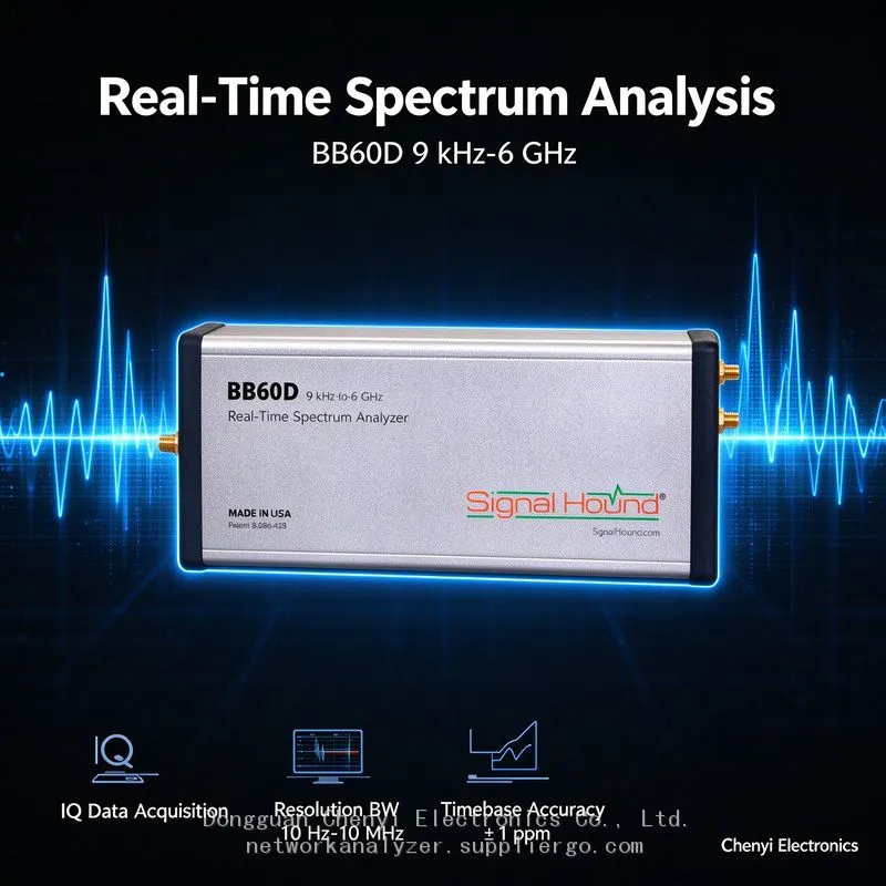
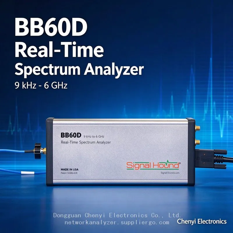
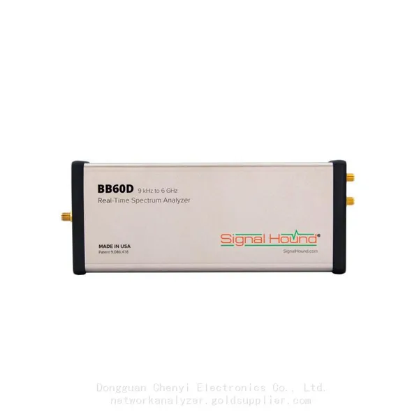
Monitoring the Satellite IF Band (950–2150 MHz) with a Signal Hound BB60D real-time spectrum analyzer supplier
Signal Hound BB60D real-time spectrum analyzer supplier
Monitoring the Satellite IF Band (950–2150 MHz) with a Signal Hound BB60D — The Moment I Feed the LNB's 13/18 V It Alarms: Bias-Tee and Preselector Setting Adaptation
Symptom
A satellite ground station / monitoring point uses the Signal Hound BB60D to look directly at the IF spectrum coming out of the LNB: ① wanting to inject LNB power (13 V vertical / 18 V horizontal, plus the 22 kHz tone) onto the line through a bias tee, users improvise all sorts of connections — some solder a supply straight in parallel, others reuse the bias port of an old receiver. Results include instrument overload alarms, abnormal noise floor, and even smoke; ② someone measuring the normal IF band feels "the preselector is blocking the signal," turns the preselector off, finds sensitivity barely improved, and suspects the setting does nothing; ③ a row of spectral lines synchronised with the 22 kHz tone appears on the display and gets reported upward as "interference from the satellite."
Root-Cause Analysis
LNB powering is DC riding on an RF line: the BB60D's SMA input tolerates DC in line with spectrum-analyzer convention (a 16 V-class DC ceiling), while LNB supply for horizontal polarisation uses 18 V — wiring 18 V directly in parallel exceeds the instrument's DC limit. Non-compliant "solder it in parallel" methods also inject supply ripple and transients.
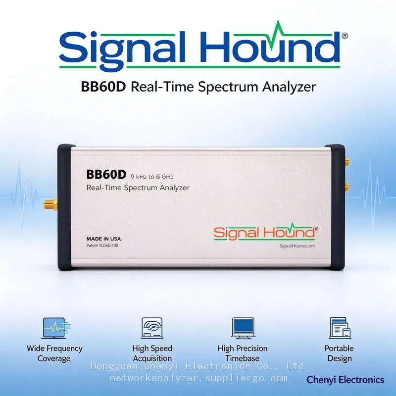
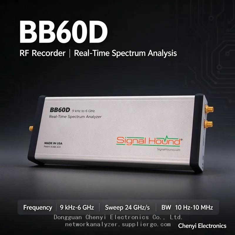
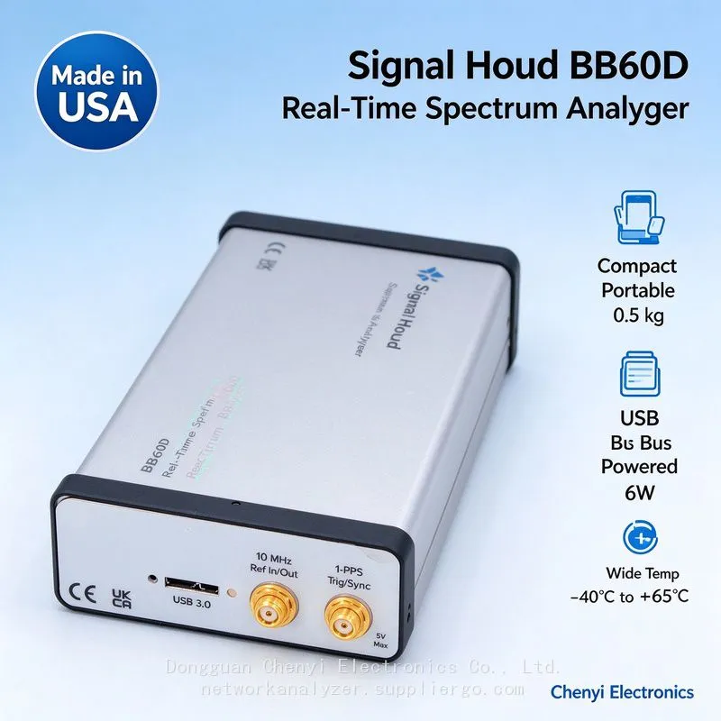
There is only one correct route: inject DC into the feed line through a bias tee (bias injection unit), and put a DC block / DC blocker capacitor on the instrument side so only the IF AC reaches the BB60D. The BB60D's preselector covers the 950–2150 MHz band within its range, so the DC block and bias-tee components must be satellite-band-rated parts covering at least 2 GHz with acceptable insertion loss and VSWR.
The 22 kHz tone lines are real signals coupled in: the 22 kHz switching tone selects between the LO's low and high bands, and its square-wave harmonics couple into the IF chain through the bias tee and the supply ground, appearing as evenly spaced comb lines on the spectrum. They are generated by the system (power-supply quality) — not by the DUT and not instrument spurs. Filtering the supply and using shielded bias cabling reduces them.
Clearing up "turning the preselector off doesn't improve sensitivity either": 950–2150 MHz sits squarely inside preselector coverage. With the preselector on you get better out-of-band rejection and a cleaner floor; turning it off merely removes out-of-band filtering and slightly lowers path insertion loss. The net difference between the two states is small and each has its use case — measure once per state with a tone plus noise floor and quantify it instead of arguing.
Compliant Wiring Scheme
Chain order: LNB feed line → splitter (one in, two out: monitoring branch + receiver branch) → the monitoring branch goes through [DC block → BB60D] in series. The power branch uses a filtered satellite bias supply, physically separated from the instrument side.
Check three component specs: splitter / DC block / bias tee must be rated to cover 950–2150 MHz and above with acceptable VSWR; the DC block's voltage rating must be ≥25 V (covering 18 V plus transient margin).
Tame the tone lines: add LC filtering at the bias supply output, run the feed-line wiring shielded and away from the instrument input. If needed, split completely into "an AC-only branch for the instrument + a biased branch for the receiver."
Settle the configuration by experiment: at the target frequency, measure noise floor and signal SNR across the four combinations of [preselector on/off × attenuation 0/10 dB], then freeze the winner as the monitoring template.
Self-check at every start-up: first confirm the instrument side shows a normal noise floor with no bias applied, then switch the bias on — this separates "instrument-side problem" from "power-coupling problem."
Acceptance Criteria
No overload alarms during 24 hours of continuous monitoring on the compliant chain; the 22 kHz harmonic comb sits at least 20 dB below the target signal; the four-state preselector comparison data is archived and the monitoring template specifies the settings explicitly.
(Based on Signal Hound BB60-series input-limit conventions (SMA +20 dBm / approximately 16 V DC, deferring to the manual shipped with the unit) and general engineering practice for satellite IF bias-fed monitoring.)
Recently Posted
-
Signal Hound BB60C IQ Recording Fails Mid-Session, Files Are Full of Gaps, or Recording Stops Early — The Problem Is the PC ,supplier
November 19, 2026Signal Hound BB60C real-time spectrum analyzer supplierSignal Hound BB60C IQ Recording Fails Mid-Session, Files Are Full of Gaps,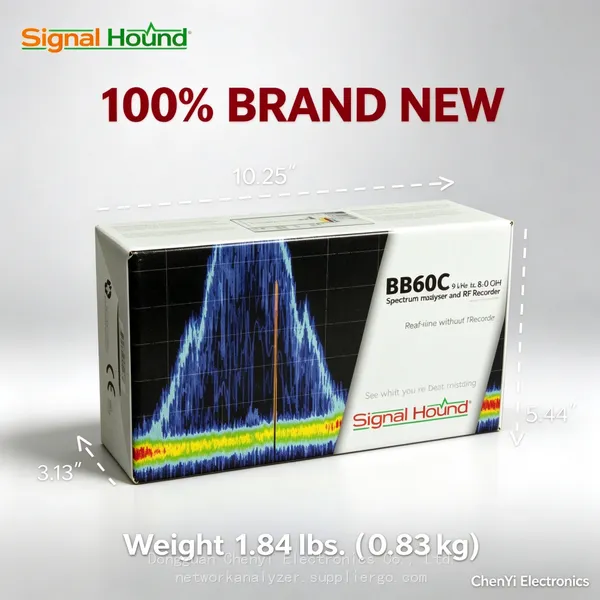 Read More
-
Signal Hound BB60C Is Plugged In but Spike Finds No Device — The LED Flashes Red/Green. How Do I Fix This? supplier
November 19, 2026Signal Hound BB60C real-time spectrum analyzer supplierSignal Hound BB60C Is Plugged In but Spike Finds No Device — The LED Flashe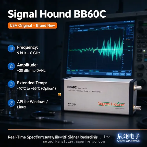 Read More
-
I Already Own a Signal HoundBB60C — Should I Move Up to the Signal Hound BB60D? Signal Hound BB60D real-time spectrum analyzer supplier
November 19, 2026Signal Hound BB60D real-time spectrum analyzer supplierI Already Own a Signal HoundBB60C — Should I Move Up to the Signal Hound BB Read More
-
The Signal Hound BB60D Still Fears +20 dBm: The Preselector Is Not a Fuse Signal Hound BB60D real-time spectrum analyzer supplier
November 19, 2026Signal Hound BB60D real-time spectrum analyzer supplierThe Signal Hound BB60D Still Fears +20 dBm: The Preselector Is Not a Fuse — Read More

Contact Us
Recommended Products
-
 Signal Hound SM200C 100 KHz to 20 GHz Real-time Spectrum Analyzer With 10GbE Monitoring ReceiversNegotiableMOQ: 1 Unit
-
Signal Hound VSG200 Vector Signal Generator 100 KHz to 20 GHzNegotiableMOQ: 1 Unit
-
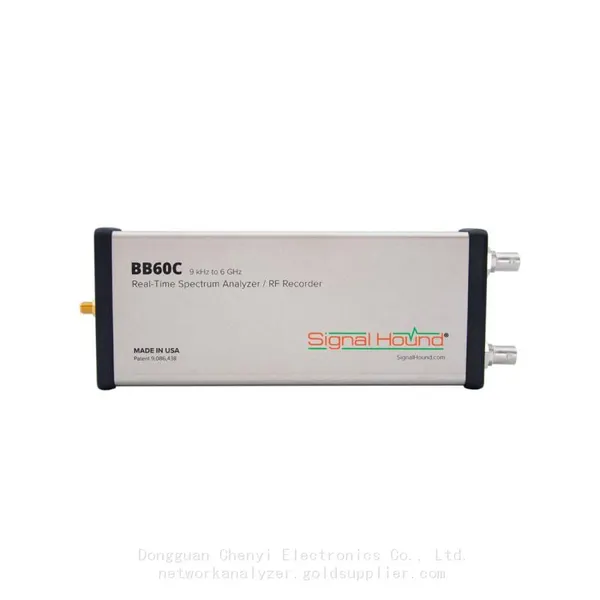
Signal Hound BB60C 9 KHz to 6 GHz Real-time Spectrum AnalyzerNegotiableMOQ: 1 Unit
-
Signal Hound BB60D 9 KHz to 6 GHz Real-time Spectrum AnalyzerNegotiableMOQ: 1 Unit
-
Signal Hound SP145 100 KHz to 14.5 GHz Real-time Spectrum Analyzer Monitoring ReceiversNegotiableMOQ: 1 Unit
-
Signal Hound VSG60A 50 MHz to 6 GHz GHz Vector Signal GeneratorNegotiableMOQ: 1 Unit
-
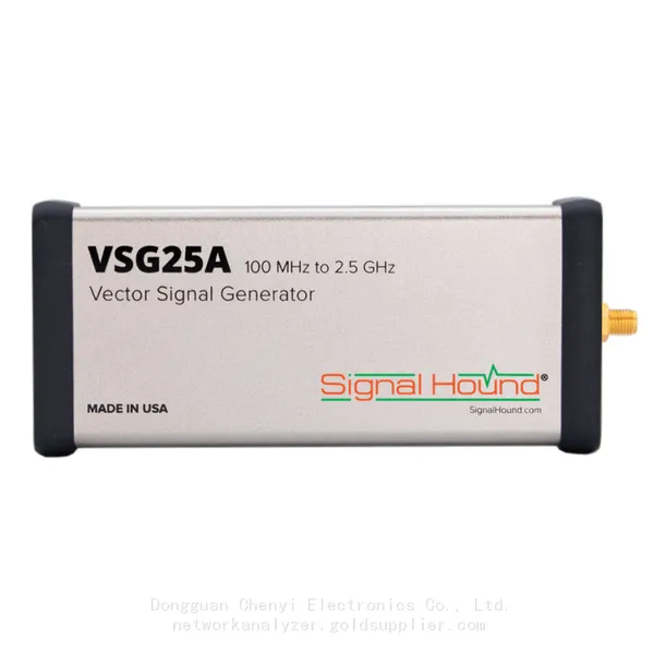
Signal Hound VSG25A 100 MHz to 2.5 GHz Vector Signal GeneratorNegotiableMOQ: 1 Unit
-
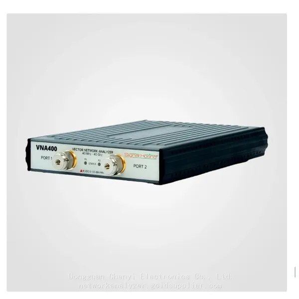
Signal Hound VNA400 40 MHz to 40 GHz 2-port Vector Network AnalyzerNegotiableMOQ: 1 Unit
-
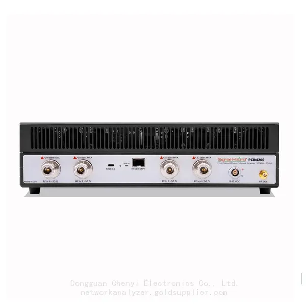
Signal Hound PCR4200 100 KHz to 20 GHz Four-Channel Phase Coherent ReceiverNegotiableMOQ: 1 Unit
-
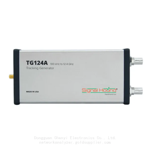
Signal Hound TG124A 100 KHz to 12.4 GHz Tracking GeneratorNegotiableMOQ: 1 Unit
-
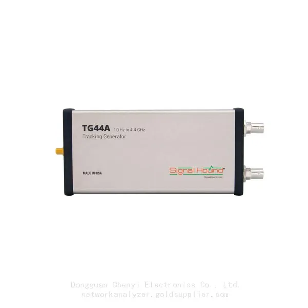
Signal Hound TG44A 10 Hz to 4.4 GHz t Tracking GeneratorNegotiableMOQ: 1 Unit
-
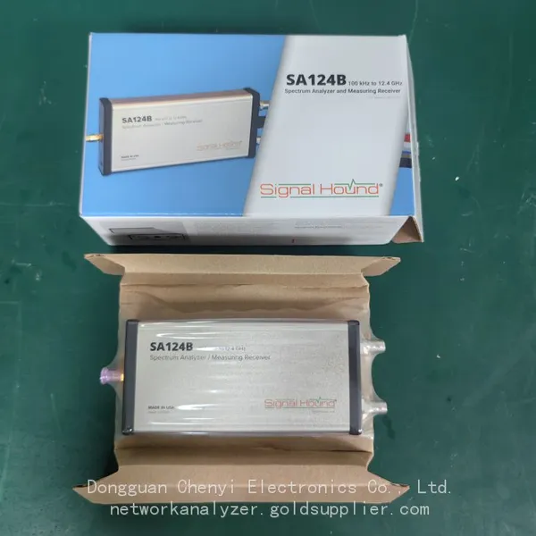
Signal Hound SA124B 100 KHz to 12.4 GHz Spectrum AnalyzerNegotiableMOQ: 1 Unit
-
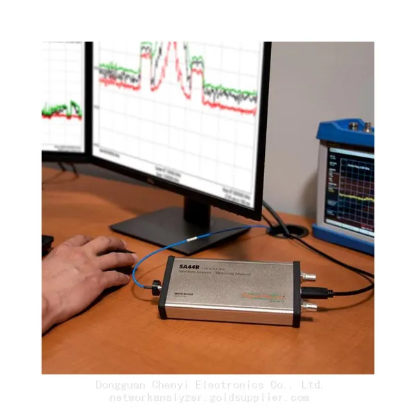
Signal Hound SA44B 1 Hz to 4.4 GHz Spectrum AnalyzerNegotiableMOQ: 1 Unit
-
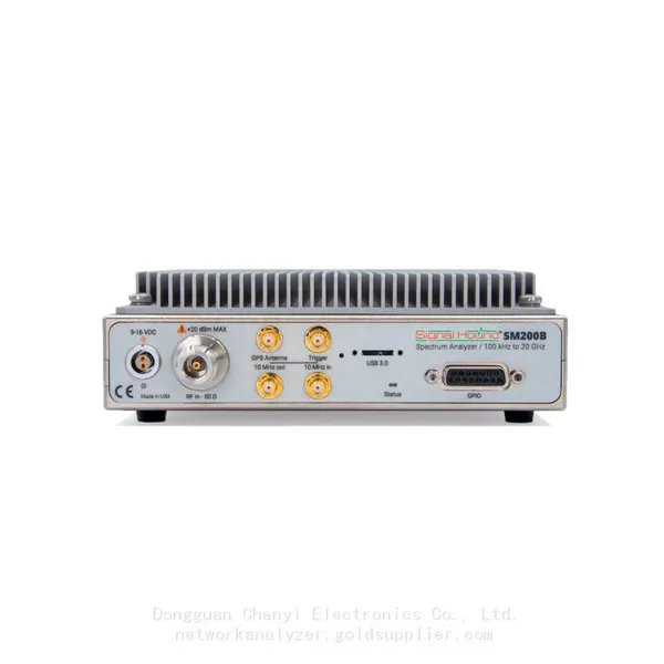
SM200B Real‑time Spectrum Analyzer,USB3.0 RTSA,100kHz-20GHz,calibrated I/Q Capture for 5G Test & Interference HuntingNegotiableMOQ: 1 Unit
-
Signal Hound SM435C 100 KHz to 43.5GHz Real-time Spectrum Analyzer With 10GbE Monitoring ReceiversNegotiableMOQ: 1 Unit
-
Signal Hound SM435B 100 KHz to 43.5GHz Real-time Spectrum Analyzer Monitoring ReceiversNegotiableMOQ: 1 Unit
-
Signal Hound PN400 Phase Noise and VCO Test System 100 KHz to 43.5 GHzNegotiableMOQ: 1 Unit
-
Keysight E4980A Precision LCR Meter 20 Hz to 2 MHzNegotiableMOQ: 1 Unit
-
Keysight E4980B and E4980BL Precision LCR Meter 20 Hz to 2 MHzNegotiableMOQ: 1 Unit
-
Keysight U1733C Handheld LCR Meter 100Hz 120Hz 1kHz 10kHz 100kHzNegotiableMOQ: 1 Unit