
 Business License

My Signal Hound BB60C Reads Several dB Off Versus Another Instrument — Where Should Amplitude Errors Be Traced From? supplier
Signal Hound BB60C real-time spectrum analyzer supplier
My Signal Hound BB60C Reads Several dB Off Versus Another Instrument — Where Should Amplitude Errors Be Traced From?
Symptom
On the same signal, the BB60C reads 3–8 dB higher or lower than a second spectrum analyzer or a power meter — beyond the published amplitude accuracy (≤±2 dB per public specs), and the error varies with frequency in no obvious pattern.
Root Cause
Amplitude errors come from three layers, and you must isolate them in order: settings layer (attenuation/gain step mismatch with signal level), connection layer (cables, adapters, connectors, mismatch), and instrument layer (calibration state or hardware). Most disputes between two "identical" measurements are settled at the connection layer.
Layered Troubleshooting
Layer 1 — Settings (5 minutes)
Fix the RF attenuation step on both instruments. Different attenuation steps have different amplitude accuracy and mismatch specs. Compare only with identical, manually set attenuation.
Check reference level and scaling. A shifted reference level or offset applied for an external attenuator (or forgotten after removing one) shifts every reading by a constant dB — the classic "everything reads 10 dB low" case.
Match detector mode and RBW. For CW signals use a suitable detector (max-hold or sample with sufficient dwell); comparing a peak-detector trace against an RMS reading introduces a systematic difference.
Verify the marker function being used — marker-to-noise vs. marker-to-marker vs. peak markers give different numbers on the same peak.
Layer 2 — Connection (15 minutes, highest hit rate)
Replace every adapter. Each cheap or worn adapter adds 0.5–2 dB of unpredictable loss and mismatch. A bent or retracted SMA center pin produces frequency-dependent errors that look exactly like an instrument problem.
Inspect center pins under magnification for retraction, off-centering, oxidation, or broken tabs. Adapters live short lives in busy labs — treat them as consumables.
Torque properly. Loose SMA connections create variable, vibration-sensitive errors; over-torque damages connectors. Use a calibrated torque wrench at the connector's rated value.
Account for cable loss. Long cables lose real dB that rise with frequency; if one instrument sits 2 m away and the other is right at the source, the difference is physics, not fault. Measure or look up cable loss and compensate on both sides.
Remember VSWR. The port VSWR spec varies with attenuation step, and mismatch between source and instrument creates standing-wave ripple that reads as a periodic error versus frequency.
Layer 3 — Instrument
Run a known-signal sweep. A calibrated signal generator at −20 dBm stepped across the band gives the truth curve. If all points sit within ±2 dB, the BB60C is fine and the earlier discrepancy came from layers 1–2.
Cross-check with a power meter at two or three frequencies — power meters are the arbiter for absolute level.
Only if the error persists with a verified source and verified cables should you suspect calibration drift or hardware. Document the error-vs-frequency curve and send the unit for factory calibration/evaluation.
Quick Triage Table
Constant dB offset everywhere → settings/offset or one fixed attenuator. Error growing with frequency → cable loss. Wavy error across frequency → VSWR/mismatch or a bad adapter. Band-specific jump → front-end filter path — instrument layer.
(Based on publicly available Signal Hound BB60C user manual and datasheet specifications.)
WhatsApp:+85268839563
WeChat :13728300615
Recently Posted
-
My Signal Hound BB60C Can't Pick Up Weak Signals Between 9 kHz and 20 MHz and Readings Keep Jumping -supplier
November 18, 2026Signal Hound BB60C real-time spectrum analyzer supplierMy Signal Hound BB60C Can't Pick Up Weak Signals Between 9 kHz and 20 M Read More
-
Spike Says My Signal Hound BB60C Firmware Is Outdated — Or My Custom API Code Errors Out. How Do I Handle Version Mismatches?supplier
November 18, 2026Signal Hound BB60C real-time spectrum analyzer supplierSpike Says My Signal Hound BB60C Firmware Is Outdated — Or My Custom API Co Read More
-
Touching a Telescopic Antenna in Dry Winter Air Killed My Signal Hound BB60C Sensitivity — Can Static Really Damage a Spectrum Analyzer?supplier
November 18, 2026Signal Hound BB60C real-time spectrum analyzer supplierTouching a Telescopic Antenna in Dry Winter Air Killed My Signal Hound BB60 Read More
-
The Signal Hound BB60C Noise Floor Looks Raised and Weak Signals Vanished — Is the Instrument Broken?supplier
November 18, 2026Signal Hound BB60C real-time spectrum analyzer supplierThe Signal Hound BB60C Noise Floor Looks Raised and Weak Signals Vanished — Read More

Contact Us
Recommended Products
-
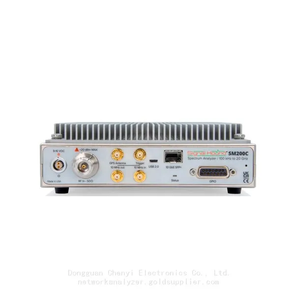
 Signal Hound SM200C 100 KHz to 20 GHz Real-time Spectrum Analyzer With 10GbE Monitoring ReceiversNegotiableMOQ: 1 Unit
-
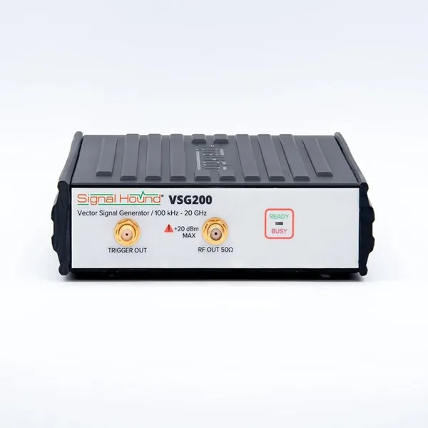
Signal Hound VSG200 Vector Signal Generator 100 KHz to 20 GHzNegotiableMOQ: 1 Unit
-
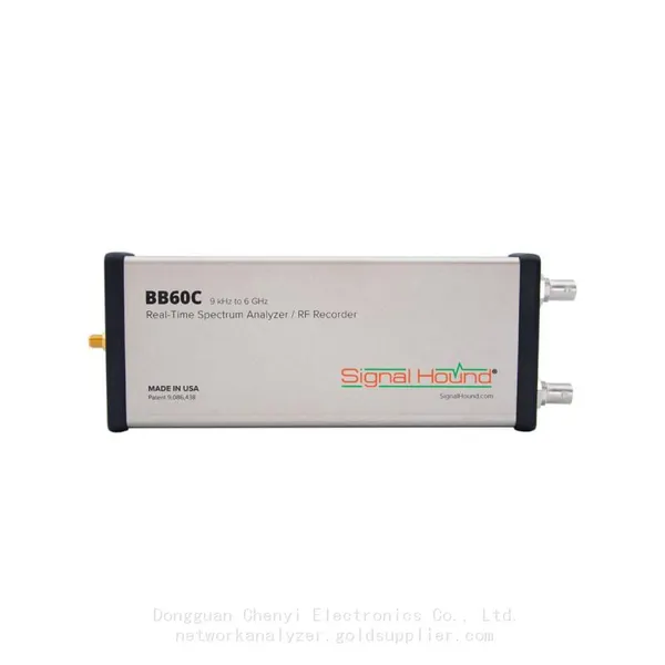
Signal Hound BB60C 9 KHz to 6 GHz Real-time Spectrum AnalyzerNegotiableMOQ: 1 Unit
-
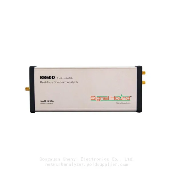
Signal Hound BB60D 9 KHz to 6 GHz Real-time Spectrum AnalyzerNegotiableMOQ: 1 Unit
-
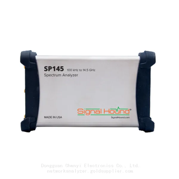
Signal Hound SP145 100 KHz to 14.5 GHz Real-time Spectrum Analyzer Monitoring ReceiversNegotiableMOQ: 1 Unit
-
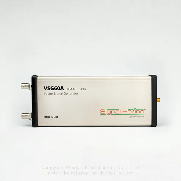
Signal Hound VSG60A 50 MHz to 6 GHz GHz Vector Signal GeneratorNegotiableMOQ: 1 Unit
-
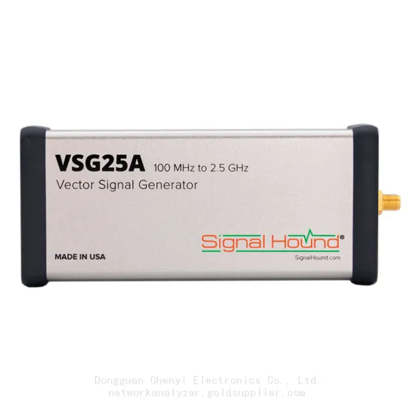
Signal Hound VSG25A 100 MHz to 2.5 GHz Vector Signal GeneratorNegotiableMOQ: 1 Unit
-
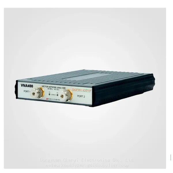
Signal Hound VNA400 40 MHz to 40 GHz 2-port Vector Network AnalyzerNegotiableMOQ: 1 Unit
-
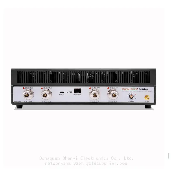
Signal Hound PCR4200 100 KHz to 20 GHz Four-Channel Phase Coherent ReceiverNegotiableMOQ: 1 Unit
-
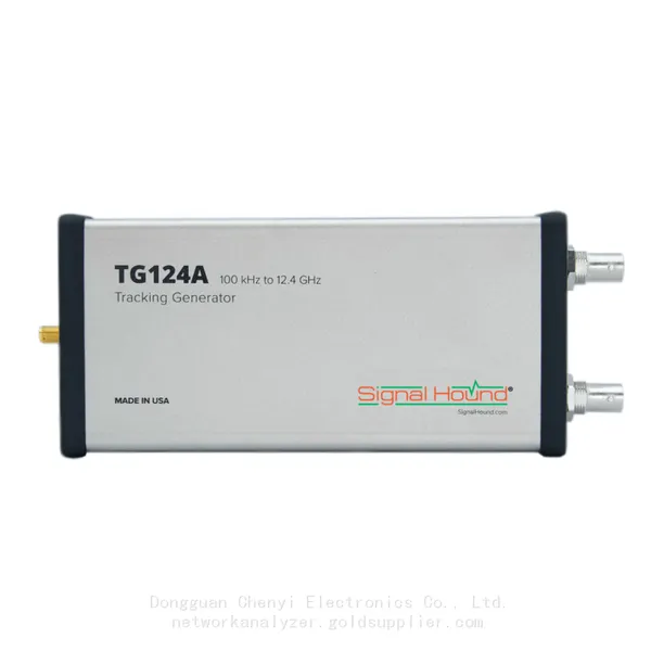
Signal Hound TG124A 100 KHz to 12.4 GHz Tracking GeneratorNegotiableMOQ: 1 Unit
-
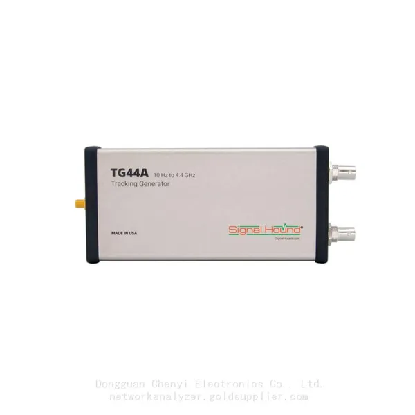
Signal Hound TG44A 10 Hz to 4.4 GHz t Tracking GeneratorNegotiableMOQ: 1 Unit
-
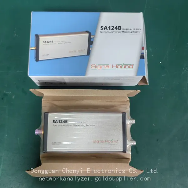
Signal Hound SA124B 100 KHz to 12.4 GHz Spectrum AnalyzerNegotiableMOQ: 1 Unit
-
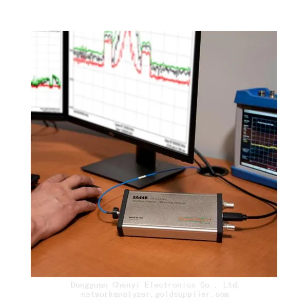
Signal Hound SA44B 1 Hz to 4.4 GHz Spectrum AnalyzerNegotiableMOQ: 1 Unit
-
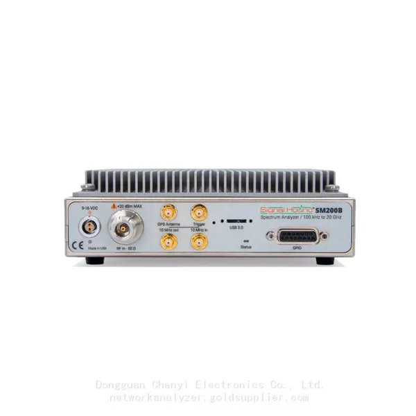
SM200B Real‑time Spectrum Analyzer,USB3.0 RTSA,100kHz-20GHz,calibrated I/Q Capture for 5G Test & Interference HuntingNegotiableMOQ: 1 Unit
-
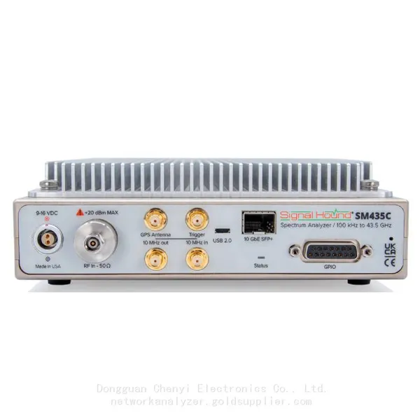
Signal Hound SM435C 100 KHz to 43.5GHz Real-time Spectrum Analyzer With 10GbE Monitoring ReceiversNegotiableMOQ: 1 Unit
-
Signal Hound SM435B 100 KHz to 43.5GHz Real-time Spectrum Analyzer Monitoring ReceiversNegotiableMOQ: 1 Unit
-
Signal Hound PN400 Phase Noise and VCO Test System 100 KHz to 43.5 GHzNegotiableMOQ: 1 Unit
-
Keysight E4980A Precision LCR Meter 20 Hz to 2 MHzNegotiableMOQ: 1 Unit
-
Keysight E4980B and E4980BL Precision LCR Meter 20 Hz to 2 MHzNegotiableMOQ: 1 Unit
-
Keysight U1733C Handheld LCR Meter 100Hz 120Hz 1kHz 10kHz 100kHzNegotiableMOQ: 1 Unit